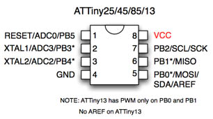


You can find schematics, or purchase kits/products that allow you to program an ATTiny chip in HV mode online. As shown in the diagram this register has 5. Not to worry, the "high" voltage is is about 12V. The configuration of ATtiny85 GPIO input pins initiates with DDRB register which helps to use PB5 pin as GPIO. Alternate Functions of Port B, that PB5 is also the reset pin, as you noted. Then we look at the DDRB to see that PB3 is the 4th bit. So we need look at the datasheet at the diagram again and see that Pin 2 is labelled as PB3.
Attiny85 port pin pb5 serial#
If the RESET pin is disabled, and the bootloader is not present, then there is another method for loading software, called "High Voltage Serial Programming". For example, let us say you want to write Pin 2 on the ATTiny85 to be an output. This means you cannot pull RESET to ground and load a program the normal way. In order to make use of all 6 non-power pins as I/O for the Trinket or Digispark, a "fuse" is set in the ATTiny chip which disables the RESET pin's normal purpose of holding the chip in reset.
Attiny85 port pin pb5 software#
If the bootloader does not find anything connected to the USB connector trying to load a new program, then it (the bootloader) starts executing from flash at the location where your program has been stored.īut, what if you want to write a new bootloader, or not have a bootloader? In that case, you can write new software using the MOSI, MISO, and SCK (clock) pins if the RESET pin is pulled to ground. The bootloader accepts new code from the host computer, if present, and writes it to a certain location in flash memory.

The bootloader checks for a certain state on the USB port of the board, to see if something is waiting to write a new program to the chip. The ATTiny chips commonly used in Arduino-like boards, such as the Adafruit Trinket or the Digispark USB will usually have a bootloader which runs before your own code.


 0 kommentar(er)
